ILI9341 Board
The ILI9341 connector PCB is a clone of the test screen PCB. So why can't we just use that and save some soldering? Well, it is too big and the connectors are in the wrong place. This is the test screen:
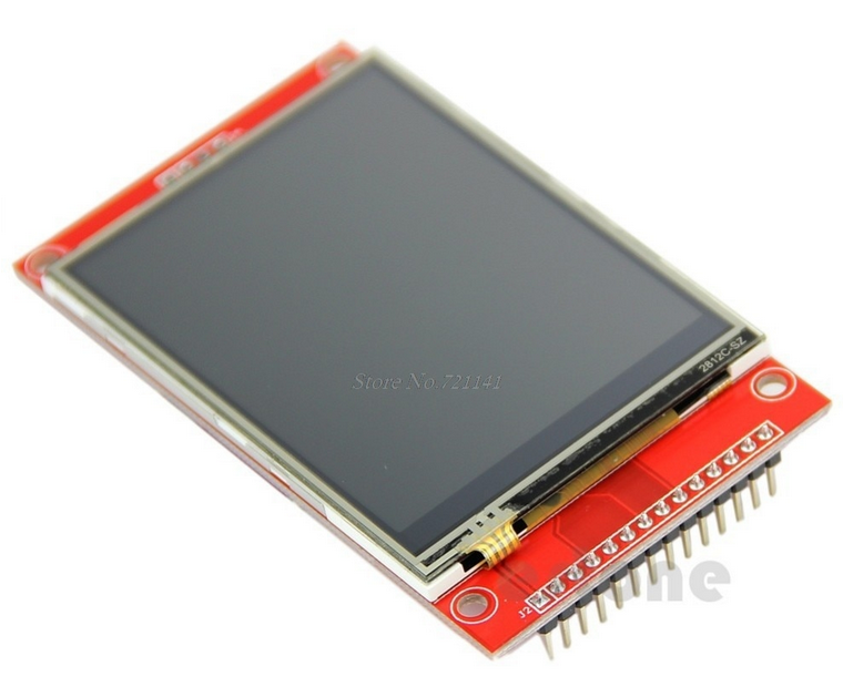
The reason it is large is that it provides a base for the screen. We don't need that because we have a 3D printed scaffold to hold the screen. And, as I said, the connectors are in the wrong place. So this is what we need:
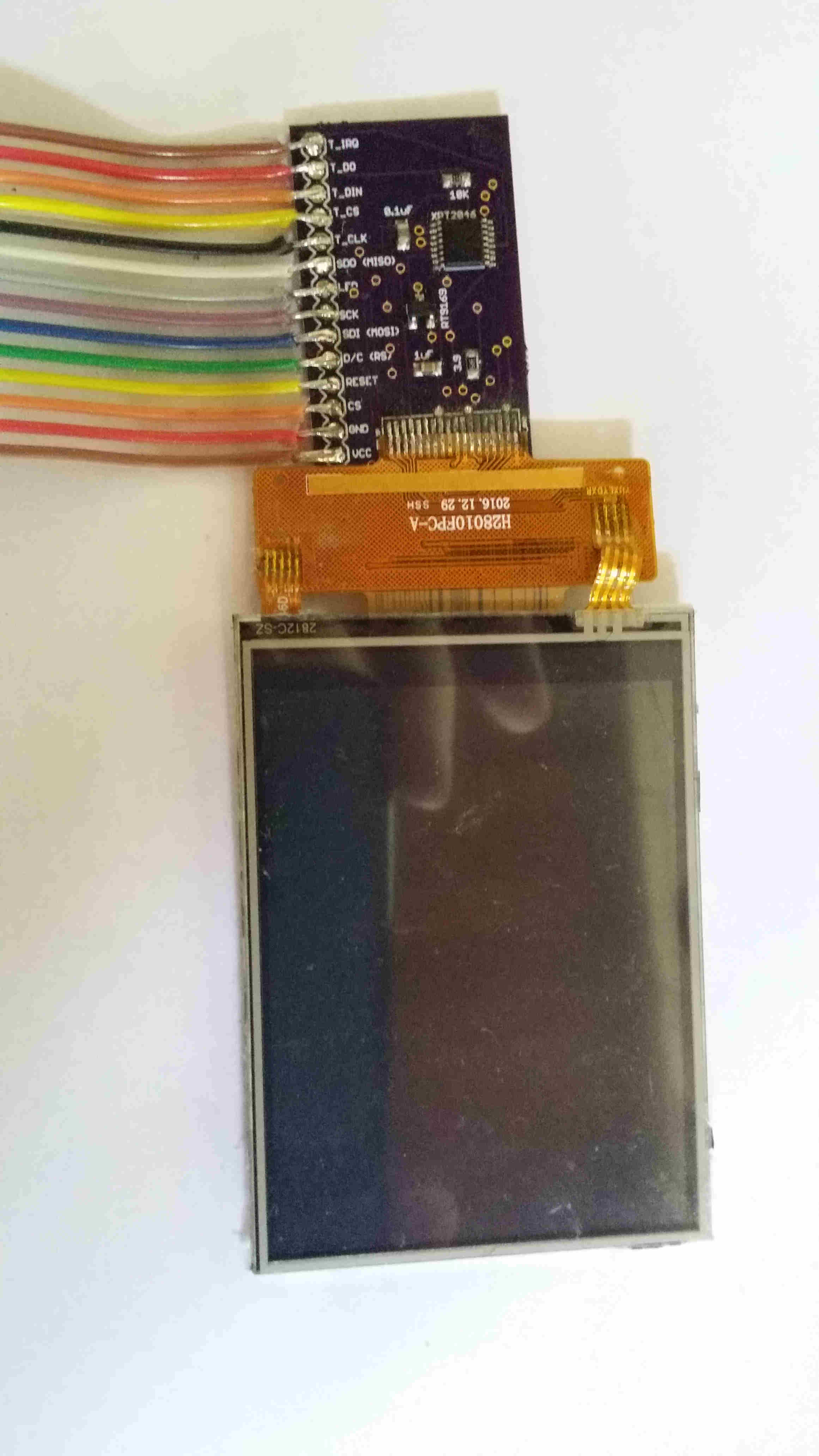
Most of the parts are SMD so if you have built the main board you already know how to do that. The only challenge is the XPT2046 IC which has a lot of connections. The rest are easy. The Eagle files for this are in github and you'll find ordering info there as well in the Readme file.
The connector on the side matches up with the connector on the main board and you can see I have added a ribbon cable to it. As with the ribbon cable on the main board this one ends in a 2.54 connector, a male one, which plugs into the female one in the other ribbon cable.
But the hardest part is getting that screen soldered to the board. The screen has a plastic strip with 18 copper pads and these need to be soldered to the 18 pads on the PCB. They are very narrow so you will need a good soldering iron and good eyesight (or a magnifying headset). Start by wiping some flux over both sets of copper pads. Then go over them both with solder and tin all the pads. Not too much solder! And be careful handling the screen's ribbon, it is fairly fragile. Once you have everything tinned you can position the two sets of pads and start soldering them together. I found it best to solder the two ends first to anchor it down and avoid twisting.
You will need, as I said, a good soldering iron with a fine tip. I use a Hakko FX-888 and a chisel tip, and there are other choices of course. However there is no choice about keeping your tip clean and properly tinned. For less fine work you can get away with oxides on your tip which limit the heat conduction, but this needs the heat right on the tip. If you aren't familiar with this check out this video
Once you have it all soldered test it out by plugging it into the main board. It should run the same samples the same way. Now fold the PCB under the screen. It should look like this:

Use some double sided tape or a little blutac to hold the two together and avoid strain on the connection. But don't press too hard on the back of the screen. I damaged one doing that and I had to solder on another one.
I've said this elsewhere but make sure you get a touch screen. There are display only screens sold in the same format and they look just the same (and a bit cheaper). Without touch, though, it would be disappointing. You want a 2.4" 240x320 SPI Serial TFT Color LCD Display Module+ILI9341 Touch Panel Screen.
Summary
This covered ordering and building the ILI9341 connector board. You've done some more SMD works and some quite challenging fine soldering to attach the screen. Then you connected this board to the main board and verified that the samples work on this new screen.