What would I do Different?
I wanted to put together a few notes on what I might do differently if I built this again from scratch.
Ribbon Cable
The cable that connects the main board to the ILI9341 connector board is rather stiff and awkward. It would be better if it were a real ribbon cable, something like this:
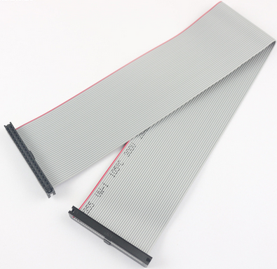
That's a 40 pin cable with plugs on both ends. It has more pins that I need but the next size down is 20 pins and I need more than that. I know these cables are more flexible and because they plug in at both ends I would be able to leave out the join in the middle of my current cable. I need 18 pins for just the screen, and another three for the control panel. But if I were doing this I would also wire the MAX30105 from the ILI9341 board and add board connections to the Teensy. My initial design for this used a different HRM mechanism which did not work well enough and the MAX30105 is a later addition that did not make it into the board design, hence the longer wires that come directly from the Teensy rather than the board.
However I would have to rework the boards at each end to use the sockets compatible with the cable ends and by the time I realised the implications of the stiffness of my cable I had already committed to the existing boards. But taking this a little further, I would add the wires for the control panel (the one with the button, speaker and LEDs) to this cable and then add connectors on the opposite edge of the ILI9341 connector board for the control board.
ILI9341 Connector
I have already mentioned that soldering the screen to the connector board is a challenge. Something I did try to make that easier was to use a connector like this:
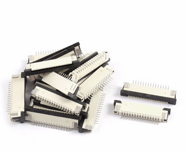
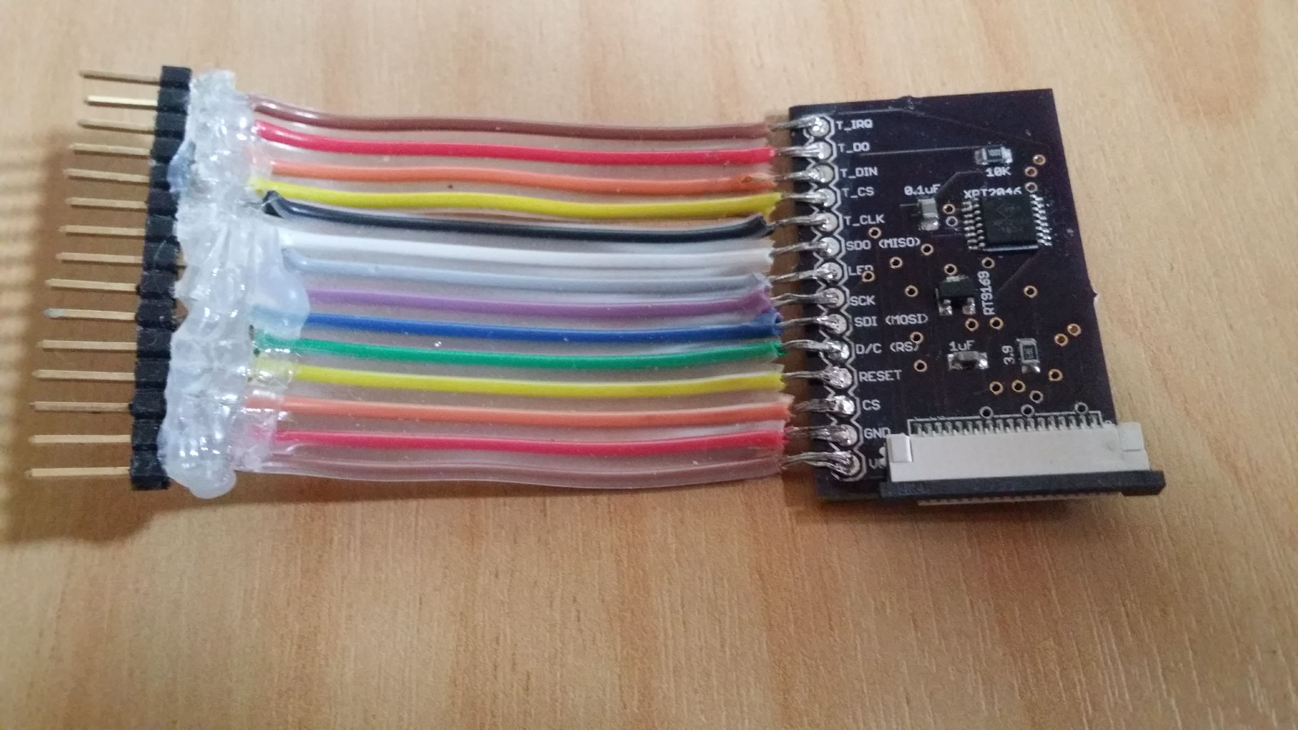
Those are 0.8mm pitch bottom contact 18pin FPC/FFC connectors and they are easy to add to the ILI9341 connector board (they are just SMD parts) and they do fit the screen connector strip perfectly. I built a board with one:
At that point I found that while the screen's connector strip slid nicely into the connector, I could not get the connector to lock well enough on it and it slipped out again. So, while this looked like an attractive solution at first, I had to discard it and go back to soldering the screen directly to the board.
USB Port
I sometimes think it would be nice to have a USB connector that did not require the device to be unstrapped from my wrist, maybe something that would plug into the side. Again, this would need some changes to the main board, and the addition of a second USB connector. Possibly this could supply power only so I could recharge the battery without removing the device, but I would need to remove it to reflash the software.
Similarly, a way to access the power switch from the outside would be nice, and adding a switch to the control panel is the obvious way to do that.
Leather Work
It turned out better than I expected, but the strap was quite difficult to get right. If I were going around again I would look for a compatible ready made strap of some kind and cut it down to use it on this. A narrow belt, for example, would probably do it.
3D Scaffold
The section that holds the main board has a gap to allow the Teensy, specifically the USB port on the Teensy, a bit more room. I left a narrow strip of plastic at the base of the gap which broke off. Next time around I would make that thicker. It meant I needed to use some sticky tape on the main board section to ensure it all holds together. The tape doesn't show when it is being worn so that's okay, but it is not as slick as I would prefer.
Also for assembly I found it necessary to cut the backs off several sections of the scaffold, so probably printing the backs separately would be smart, maybe even having a way to snap them together rather than glueing them back. And maybe a smarter way to lock the sections together would be good too.