I’ve been building a tiny connector board for an ILI9341 LCD. For the uninitiated this is the specification for a small display screen.What I am doing here is reproducing this red board with screen:

which is all explained perfectly well, including how to wire it up to a Teensy, on the PJRC page.
The trouble is that red board is too big for my project. I have just enough room for the screen but not for the rest, so I have to reverse engineer it. Also that board has an SD reader on the back of it which is no use to me. I just need a screen and I need touch, and I need it attached to a board as small as I can manage.
The screen implements an interface called ILI9341 and there seem to be several variations on that in terms of how many connectors the actual screen needs. Some are 50, some are 14. They all have a ribbon cable coming out of the screen with approximately 1mm connectors you need to hand solder (unless you have a much more sophisticated setup than I do). These variations are usually hidden from you if you buy something like a red board because you only need to worry about the pinouts on that board.
You can buy the bare screen that the red board uses here. It has 14 screen connections as well as some SMD parts soldered right onto the ribbon cable that comes out of the screen. My understanding is that this reduces the number of connections you need to solder down to the 14 it uses. Because it is a touch screen it has 4 more connections too, so a total of 18. Still better than 50.
My circuit includes a RT9169 which ensures the voltage is 3V. The screen is sensitive to the voltage. I did not try it on 3.3V, which is what the rest of my circuit runs on because I don’t want to fry a screen, I just added the regulator. If you are using a touch screen then you also need an XPT2046 touch controller. This takes the signals from the touch panel and translates them. Other than that you only need a couple of resistors and a couple of ceramic capacitors. If you are not using a touch board you can leave off the touch controller and don’t bother wiring the T_ pins.
The ILI9341 interface can be used in two ways. One has 8 data lines and may be faster, the other uses SPI and is quite fast enough for my needs and is used here. I use SPI for both the screen and the touch interface.
The only other thing to be careful of is to get the ribbon cable the right way around. The ribbon is marked with a (tiny) ‘1’ on one side and I numbered the connectors on the pad. Even so this picture should help:
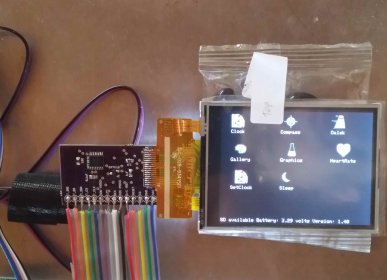
You can see the yellow ribbon cable attached to the board. The ribbon cable is fragile and fiddly to solder, but not impossible if you take care. But you should do the SMD parts first, then you can use solder paste and heat the whole board without damaging the screen. I put some solder paste onto the ribbon cable connection to tin it and then I soldered the cable onto that with a soldering iron. You should consider folding the board under the screen and fixing it there with double sided tape. That will remove any strain on the ribbon cable. It is also what the red board does.
The Eagle files for this are on my github repo and you can order the board from OSHPark.