A while ago I posted a breadboard friendly breakout board for the ESP8266-01 along with a breadboard circuit to flash it. Since then I turned that circuit into a board which you can order from OSHPark for a few bucks.
![]()
This post is about how I use it. It is, of course, similar to the breadboard example, but worth documenting properly. The full setup requires the board itself, of course, an ESP8266-01 and an FDTI which you can get from Sparkfun. Make sure you get the 3.3V FDTI, the 5V version will fry your ESP8266-01.
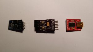
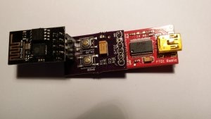
The first picture shows the three components separated and the second has them plugged together. I use two 2.54mm Jumper Cap Mini Jumpers to attach the ESP to the board rather than solder it on permanently, which would be dumb. Using this I can flash the ESP from the Arduino IDE. Setting up the Arduino IDE is easy. Once set up you want to select the ‘Generic ESP8266 Module’ board in the Arduino IDE.
To flash you launch the build from Arduino and hold down the GPIO0 button (that’s the bottom button in the pictures) until you see the “…” showing it is loading, then you can release it. The ESP will restart when it loads. The other button (CH_PD) earths the CH_PD pin and that will wake up the ESP if your program has put it into deep sleep. I use this for testing my programs.
In the Arduino IDE I select the board "Sparkfun EPS8266 Thing" rather than the Generic ESP8266. Even though I am not using the Sparkfun product that is the setting that worked. Also the Programmer should be set to "Arduino as ISP".
You can find the Eagle files on Github.