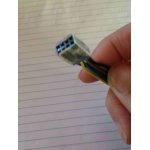
If you’ve been messing around with ESP8266 boards (and who hasn’t?) you’ll have noticed that the ESP8266-01 does not play well with a breadboard. There are various ways around this using perf boards or female-male jumper leads. For example I taped 8 of the female ends together and it works but there is enough confusing stuff going on without an awkward bread board layout.
So I got onto Eagle and produced this:
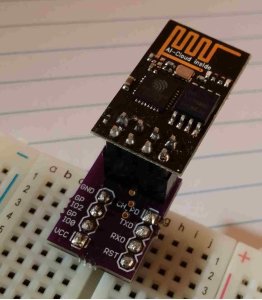
It is a really simple breakout for the ESP8266-01. There are no SMD parts, just normal header pins and two 2.54mm Jumper Cap Mini Jumpers. That’s a little soldering but just easy through-hole stuff. Note that using the Jumpers means you do not need to solder your ESP8266 into the breakout. You just plug it in. You’ll see why this is important soon. You can order the breakout from OSH Park for a couple of bucks (none of which comes to me, I’m happy to share).
Once you have this what do you do with it? Well, this is what I did:
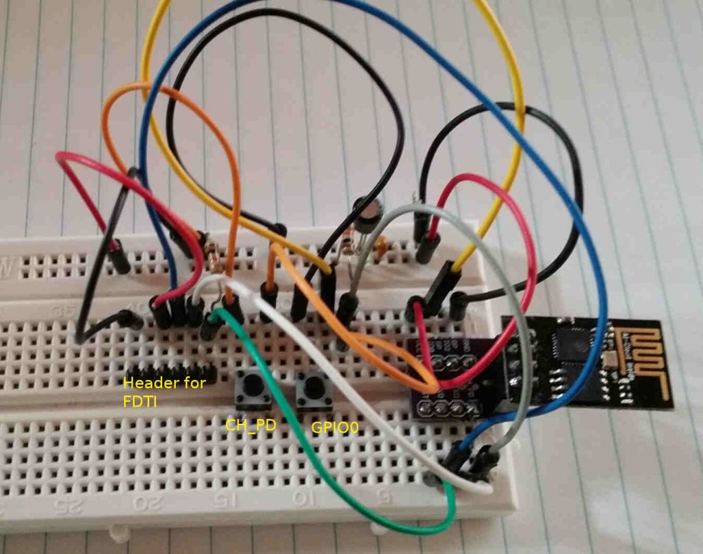
Using this I can flash the ESP from the Arduino IDE. I plug the Sparkfun FDTI into the header (GND on the left, DTR in the right). Setting up the Arduino IDE is easy.
Here’s the circuit schematic:
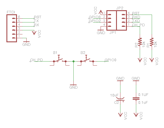
I found the resistor on the RST (R2) doesn’t make any difference but others have used it so I added it.
To flash you launch the build from Arduino and hold down the GPIO0 button until you see the “…” showing it is loading, then you can release it. The ESP will restart when it loads. The CH_PD button earths the CH_PD pin and that will wake up the ESP if your program has put it into deep sleep. I use this for testing my programs.
In the Arduino IDE I select the board "Sparkfun EPS8266 Thing" rather than the Generic ESP8266. Even though I am not using the Sparkfun product that is the setting that worked. Also the Programmer should be set to "Arduino as ISP".
Make very sure you use a 3V FDTI. If you use a 5V one you will fry your ESP.
This circuit shows power coming from the FDTI and you might find that it doesn’t supply enough current. In that case disconnect the 3V3 pin from the FDTI and connect a second 3V supply to that wire instead. Again, make sure it is 3V supply, not a 5V supply.
If you have several ESPs to flash you can do them with this circuit because you can unplug your ESP from the breakout and connect it to whatever you want to deploy it. That’s why I used those jumpers.
I’ve put the Eagle files into Github.