I’ve posted here before about my Beaglebone home server. A Beaglebone is like a Raspberry Pi, a tiny computer that runs Linux, doesn’t need a disk drive, keyboard, screen or fans. Also quite cheap. I use one as a home server because I am happy to leave it running 24 hours a day knowing it isn’t burning much power. And it monitors the various wifi devices around my house. Specifically it lets me know when the snail mail arrives (it is a long way to the gate) and when visitors arrive. When these events happen it sounds a chime.
The reason I went for Beaglebone rather than the Raspberry Pi almost everyone else is using is that it has more GPIOs, ie programmable pins, meaning I can operate more devices. There are heaps of them, but since I am so far only using one GPIO I could have used a Raspberry Pi just as easily.
The chime is recycled from an old electronic doorbell that never worked too well but the chime itself is fine. There are some small complications in that it needs 5v to run and the GPIOs on the Beaglebone are only 3.3v, it does have a 5v supply as well, so it is simple enough to hook up a transistor to act as a switch. Here’s the circuit:
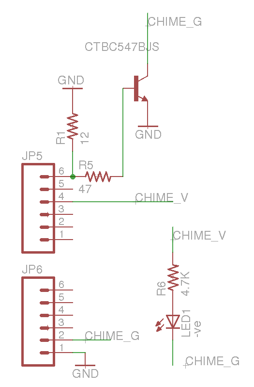
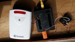
I have an LED light up when the signal arrives and a recent addition is the pull down resistor between the GPIO. I’ve had it sitting on the window sill for over a year in breadboard mode working tolerably well but looking quite ugly. I finally got around to getting a PCB made for this to make it look a bit better. The picture below shows what it looks like now, and I have the remains of the old breadboard, no longer needed, sitting beside it for comparison. So the trailing wires etc are done with now.
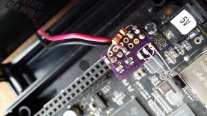
Here’s a close up of the PCB
Initial attempts at this gave me some strange results. On the breadboard setup I had noticed the chime would click a few times when the Beaglebone rebooted. Not an issue, but on the PCB it changed to a long series of annoyingly loud pips. It took me a while to figure out that this is caused by the GPIO having a random voltage during the early parts of the boot sequence, enough to trigger the chime, kinda. Once the boot completes it settles down and works normally. It wouldn’t be much of a problem except that the BB sometimes reboots for no reason. It comes back up just fine and it only does it every week or so, but when it does it in the middle of the night the annoyingly loud pips are not welcome. So I had to solve this.
The answer is to add a pull down resistor on the GPIO. That’s the 12 ohm resistor you can see in the circuit. Because I had to figure this out as I went the pull down resistor did not make it into the PCB and I added it later when I knew what the value needed to be, using trial and error. I suspected the transistor for a while, and tried several of those, and ended up using the same transistor I used on the breadboard because I knew that worked. So the PCB is still a little untidy, but much better than the breadboard.
There’s some code involved in all this but it is very simple. To set the signal to high I use a bash command:
echo 1 > /sys/class/gpio/gpio60/valueand a similar echo 0 to set it low again. The rest of the system is an nginx server running on the beagle bone which accepts REST calls from the various devices and handles them in PHP. As I’ve described elsewhere and incoming call is examined to see who it came from and, for those that need it, the chime is invoked. Most devices (vermin traps) just need logging and a simple web page displays the log to any browser in the house.